Friday, October 4, 2024

How to block web pages

I block myself from certain web pages because I find they hinder my productivity or because I'm mad at them for some long-forgotten reason.

The original way I blocked web pages was to make changes to the hosts file at the location below.  You'll need to run notepad as administrator and then open the "hosts" file (no extension).

C:\Windows\System32\drivers\etc\hosts

The operating system resolves DNS names to host names by first looking in the hosts file and then doing a DNS lookup on your configured DNS server.  Recall that 127.0.0.1 is your local host.  So if you add lines like the ones below, you tell the operating system to look to itself when it attempts to open web pages like the ones I specified here:

127.0.0.1 i.imgur.com
127.0.0.1 imgur.com

127.0.0.1 www.digg.com
127.0.0.1 digg.com

This blocks your computer from accessing the websites specified above.  If you ping the hostnames, you'll see it resolves to 127.0.0.1.

This used to work - and still does.  However, SOME browsers now bypass local DNS lookups from the operating system and do lookups by themselves using https and protocols other than the traditional DNS lookup.  The idea here is that it prevents third parties from snooping on your hostname lookups in clear text, forcing the browser to use https instead.  The problem with this approach is that it breaks decades of traditional hostname resolution.  The browser no longer honors my local hosts file.  You can disable the feature - details here:

https://support.mozilla.org/en-US/kb/firefox-dns-over-https

Thinking about this... what if you want to block only certain websites but still want the advantage of secure lookups?

Here is a way. You can force Firefox to block websites by adding domain names to a local policy file here:

C:\Program Files\Mozilla Firefox\distribution\policies.json

You'll need to run notepad as admin and then open the file.  Create the following block of config code:

{
  "policies": {
    "WebsiteFilter": {
      "Block": ["*://*.evilcorp.com/*",
"*://*.googlesucks.org/*",
"*://*.facebook.com/*"]
    }
  }
}

The code above would block evilcorp.com, googlesucks.org, and facebook.com

Notice when commas are needed and when they are not.  The last line does not need a comma.

Once you create the file, save it, make sure you closed out of Firefox, and then launch a new Firefox window.  Go to the offending website and it should tell you that it is blocked.

Chrome and Edge probably have similar mechanisms.  I only use Firefox for my general web browsing, so I only figured it out on Firefox.


Wednesday, July 17, 2024

Cisco 137 - Ansible, Puppet, and Chef

Ansible
Model: PUSH = Agentless
Action file: Playbook
Protocols: SSH & NETCONF
Uses YAML.
Written in Python.


Puppet

Model: PULL = Requires Agent (or proxy)
Action file: Manifest
Protocols: HTTPS(REST) TCP port 8140
Written in Ruby

Example of Puppet DSL resource declaration:

sudo::conf { 'CoAdmins':
ensure    => present,
content    => '%admin ALL=(ALL) ALL',
}


Chef

Model: PULL = Requires Agent
Action file: Recipe, Runlist
Protocols: HTTPS(REST) TCP port 10002
Written in Ruby

Example of Chef recipe:
sudo "CoAdmins"
    group "CoAdmins"
    nopasswd true


Ansible's playbooks use an imperative language, whereas Puppet uses a declarative language.

Adoption numbers:

Wendell Odom's book says Ansible > Puppet > Chef

Jeremy says Ansible is the most popular choice for network device config management

Boson ExSim says Puppet is most mature and widely used


Tuesday, July 16, 2024

Cisco 136 - Python lists and dictionaries

list1 = [ "g0/0", "g0/1", "g0/2" ]

dictionary1 = { "config_speed" : 'auto',

    "config_duplex" : "auto",

    "config_ip" : "10.1.1.1" }


^ Notice dictionary uses key:value pairs


Cisco 135 - CRUD and REST

CRUD - REST (HTTP) Verb

Create    POST

Read    GET

Update    PATCH, PUT

Delete    DELETE


Cisco 134 - JSON, XML, YAML

---------------> JSON <---------------

JavaScript Object Notation
Attempts to strike balance between human-readable & machine readability
{
  “response” : {
    “type” : “Cisco Catalyst 9300”,
    “family” : “Switches”,
    “macAddr” : “f8:7b:20:67:62:80”
  }
}

Key:Value Pair
Value types:
- Text
- Numeric
- { } Object - Series of key:value pairs
- [ ] Array – Series of values (not key:value pairs)

Example of JSON Array:
[
“Fred”,
“Wilma”,
“Barney”
]

Example of JSON Object:
{
    “Parents”: [
        “Fred”,
        “Wilma”,
        “Barney”,
        “Betty”
    ],
    “Children”: [
        “Pebbles”,
        “Bambam”
    ]
}
^ This JSON object has two arrays within.

---

---------------> XML <---------------

eXtensible Markup Language
<?xml version = “1.0”>
<root>
    <blah>
        <blah1>
        <blah2>
        <blah3>
    </blah>
</root>

---

---------------> YAML <---------------

YAML Ain’t Markup Language
Used heavily in Ansible
#Comment about Playbook
-name: Get IOS Facts
    hosts: mylab
    vars:
        host:  “{{ ansible_host }}”
        username: “{{ username }}”
tasks:
    - ios_facts:
        gather_subset: all
        provider: “{{ cli }}”


Saturday, June 8, 2024

Cisco 133 - DAI = Dynamic ARP Inspection

Recall that ARP = Address Resolution Protocol.
It translates IP addresses to MAC addresses.

ARP Request/
ARP Reply

Gratuitous ARP - An ARP reply sent without receiving an ARP request.
Sent to the broadcast MAC address.
Allows other devices to learn the MAC address of the sending device without them having to send ARP requests.
Some devices automatically sent GARP messages when interface is enabled, IP address changes, or the MAC address changes.

DAI (Dynamic ARP Inspection) is a security feature of switches that is used to filter ARP messages received on *untrusted* ports.
Only filters ARP messages.  Non-ARP messages are not affected.

By default, all ports are *untrusted*.

Recommendation: All ports connected to other network devices (switches, routers) should be configured as *trusted*.  Interfaces connected to end hosts should be *untrusted*.

DAI inspects the sender MAC and sender IP fields of ARP messages received on untrusted ports and checks that there is a matching entry in the DHCP snooping binding table.

SW1#show ip dhcp snooping binding
^ Displays a 1:1 mapping of MAC addresses to IP addresses and which VLAN and Interface the belong to.

If there is a matching entry, the switch forwards the message normally.
If no matching entry, the ARP message is discarded.

ARP ACLs can be manually configured to map IP address/MAC addresses for DAI to check.  This is needed for hosts that don't use DHCP.

DAI can be configured to perform more in-depth checks.  It also supports rate-limiting.

SW2(config)#ip arp inspection vlan 1
^ Enables DAI on VLAN 1.  
No global config.
You'll need to enable it on each VLAN used.

SW2(config#)ip arp inspection vlan 1
SW2(config#)int range g0/0 - 1
SW2(config-if-range)#ip arp inspection trust
^ Set of commands turns on DAI for VLAN 1 and then sets the range of interfaces specified as trusted.

SW1#show ip arp inspection interfaces
^ Displays all interfaces and whether they are trusted or untrusted.  Also shows allowed rate (packets per second) and allowed burst interval (X packets per Y seconds).

If ARP messages are received faster than permitted, default is to shut down the interface with err-disabled.
To re-enable:
- shut/no shut
- errdisable recovery cause arp-inspection

Optional checks:

SW1#(config)#ip arp inspection validate <type>
Where <type> can be:
dst-mac = Validate destination MAC address
ip = Validate IP address
src-mac = Validate source MAC address

If you want all three, you must specify all three on the same command line:
SW1#(config)#ip arp inspection validate dst-mac ip src-mac
^ Configures all three deeper inspection types.

You'll need to add non-DHCP clients to the dhcp snooping binding table:

SW2(config)#arp access-list ARP-ACL-1
^ Create an ACL
SW2(config-arp-nacl)#permit ip host 192.168.1.100 mac host 0c29.2f1e.7700
^ Define an entry in the ACL
SW2(config)#ip arp inspection filter ARP-ACL-1 vlan 1
^ Applices the ACL to VLAN 1
You'll need to do this on each VLAN as appropriate.

SW2#show ip arp inspection
^ Displays info and statistics about DAI state, configuration, and counters.


[These are my notes from Jeremy's excellent CCNA course which can be viewed here.]

Cisco 132 - DHCP Snooping

Turns on features that look for and discard misbehaving DHCP packets.

Enable on "untrusted" ports (those downstream from the real DHCP server -- typically facing end user devices).

SW2(config)#ip dhcp snooping
^ Globally turn on DHCP Snooping

SW2(config)#ip dhcp snooping vlan 1
^ And turn it on for each VLAN - in this case, VLAN 1.

SW1(config)#no ip dhcp snooping information option
SW2(config)#no ip dhcp snooping information option
^ Turns off the default behavior of both switches to add "Option 82" to DHCP messages they receive from clients.

R1 <--> SW2 <--> SW1 <--> PC1

By default, Cisco switches will drop DHCP messages with Option 82 that are received from an untrusted port.  In a design like the one above, SW1 would (by default) add Option 82 even if it is not the relay agent.  When the upstream switch (SW2) receives this packet from a downstream (untrusted) port, SW2 takes the default behavior which is to drop DHCP messages with Option 82 that are received from an untrusted port.

By running the command above, we tell the switch not to add Option 82.


SW2(config)#int g0/0
SW2(config-if)#ip dhcp snooping trust
^ Configures this port as a "trusted" port.  Trusted ports won't perform DHCP Snooping.  Do this on each port that points "toward" the real DHCP server.

SW1#show ip dhcp snooping binding
^ Displays the DHCP Snooping binding table which is loaded with known DHCP info:
MacAddress - MAC of client
IpAddress - IP given to client
Lease - Length of DHCP lease
VLAN - Which VLAN
Interface - Interface of leased IP configured on a MAC

Rate-Limiting:

SW1(config)#int range g0/1 - 3
SW1(config-if-range)#ip dhcp snooping limit rate 1
^ This limits the DHCP traffic rate to 1 per second.  This is too low in a real network.  If the traffic rate exceeds this number, the interface will be disabled.

Manually re-enable interface with shut/no shut or configure interface to automatically re-enable:

SW1(config)#errdisable recovery cause dhcp-rate-limit
^ Turns on recovery of interface in (default) 300 seconds if reason is surpassing DHCP rate

SW1#show errdisable recovery
^ Confirms automatic recovery is turned on by displaying which errDisable reasons are enabled


[These are my notes from Jeremy's excellent CCNA course which can be viewed here.]

Cisco 131 - Port Security

If unauthorized source MAC address enters a port, default action is to place interface in 'err-disabled' state.  End result is like the interface is shut down.

If port security is enabled on an interface, by default only a single MAC address is allowed:
- The first source MAC address that enters the interface (dynamically learned)
- Or you can configure the MAC address manually

You can change the max number of MAC addresses allowed.  For example, when connecting a PC through an IP phone to a switch interface, you need to bump up the max MAC addresses to two to allow both devices to use the interface.

Rather than manually specifying the MAC addresses allowed on each port, port security's ability to limit the number of MACs allowed on an interface is more useful.  This helps against DHCP starvation attacks.  This also prevents the switch MAC address table from getting filled up.

SW1(config)#int g0/1
SW1(config-if)#switchport port-security
^ This is the simplest command to turn on port security.   However, if g0/1 is running switch defaults, the default is to run as a dynamic port.  This means the command will be rejected because you cannot run port security on a dynamic port.

Port security can be enabled on access or trunk ports, but they must be statically configured as access or trunk.  They cannot be dynamic.

switchport mode access = OK
switchport mode trunk = OK
switchport mode dynamic auto = NOT OK
switchport mode dynamic desirable = NOT OK

Confirm the port is running in dynamic auto mode:

SW1#show int g0/1 switchport
Name: Gi0/1
Switchport: Enabled

Administrative Mode: dynamic auto
Operational Mode: static access

So we need to flip the port to access mode:

SW1(config-if)#switchport mode access

Confirm switch no longer runs in dynamic access mode:

SW1#show int g0/1 switchport
Name: Gi0/1
Switchport: Enabled 
Administrative Mode: static access
Operational Mode: static access

Now we can enable port security:
SW1(config-if)#switchport port-security
^ Turns on port security on an interface.  It will use default port security settings.

SW1#show port-security int g0/1
Port Security: Enabled
Port Status: Secure-up
Violation Mode: Shutdown
Aging Time: 0 mins
Aging Type: Absolute
SecureStatic Address Aging: Disabled
Maximum MAC Addresses: 1
Total MAC Addresses: 0
Configured MAC Addresses: 0
Sticky MAC Addresses: 0
Last Source Address: Vlan: 0000.0000.0000:0
Security Violation Count: 0

Notice:
Violation Mode: Shutdown
^ This means the port will shut down if unauthorized MAC is used.

Possible settings for Violation Mode - notice these are alphabetical in order of enforcement/disruption:

    Protect - Switch discards unauthorized traffic, does not shut down the interface, does not log the violation, and does not increment the violation counter.

    Restrict - Switch discards unauthorized MAC addresses. Does NOT disable interface but logs the violation.  Violation counter is incremented by 1 for each unauthorized frame.

    Shutdown - Default - Shuts down port with Err-disabled state and generates a Syslog/SNMP message.  Violation counter will be set to 1.


To manually re-enable the interface after a violation has occured:

First disconnect the unauthorized device.  Then:
SW1(config)#int g0/1
SW1(config-if)#shutdown
SW1(config-if)#no shut

You can configure the switch to automatically re-enable a port after a period of time.  There are many reasons a port can enter an 'ErrDisable' state.  Only one of them is 'psecure-violation' (port security violation).  

SW1#show errdisable recovery
^ Shows all the possible reasons a port can go into errdisable state, including psecure-violation:

ErrDisableReason    Timer Status
psecure-violation    Disabled

Disabled = No timer (this is the default)

If "err-disable recovery" is enabled, the default is to re-enable the disabled interface after 5 minutes.

SW1(config)#errdisable recovery cause psecure-violation
^ Enables recovery (will re-enable disabled port for cause "psecure-violation" after 5 minutes.

SW1(config)#errdisable recovery interval 180
^ Drop the timer down to 3 minutes.

You can manually configure the authorized MAC address on a port:
SW1(config-if)#switchport port-security


Recall the default violation mode is Shutdown.  You can change this:

SW1(config-if)#switchport port-security
^Turns on port security

SW1(config-if)#switchport port-security mac-address 000a.000a.000a
^Sets the authorized MAC address

SW1(config-if)#switchport port-security violation restrict
^ Changes from default of shutdown to restrict mode.

MAC address aging:

MAC addresses dynamically learned or statically configured on a port security enabled port are called secure MAC addresses.  By default, they don't age out.  No timer.

You can change that behavior:

switchport port-security aging time <minutes>
^ Changes the age out time for learned addresses.

Aging Type:
switchport port-security aging type {absolute | inactivity}
^ Sets the aging type:

Absolute = Default = After the secure MAC address is learned, the aging timer starts and the MAC is removed after the timer expires even if the switch continues receiving frames from that source MAC.
Inactivity = Like regular MAC address aging, aging timer starts when learned but is reset every time a frame from that source MAC address is received on that interface.

By default, static configured MAC addresses won't age out.  You can over-ride this behavior so the switch will age them out just like dynamic addresses:

switchport port-security aging static

Sticky Secure MAC Addresses:

SW1(config-if)#switchport port-security mac-address sticky
^ Dynamically-learned secure MAC addresses will be added to running config like this:
switchport port-security mac-address sticky <mac-addr>

These 'sticky' secure MAC addresses will *never* age out - even if you enable static aging.  However, they are added to the running config, not the startup-config.  So you will need to save the running-config to make them truly permanent or you will lose them at next switch reboot.

Sticky and static secure MAC addresses will have a type of STATIC in MAC address table.

#show mac address-table secure
^ Displays all secure MAC addresses


[These are my notes from Jeremy's excellent CCNA course which can be viewed here.]

Friday, June 7, 2024

Cisco 130 - Detour into VOIP phones

Recall that a Cisco phone has this design:

PC <---> IP Phone <--> Switch SW1

^ The IP Phone acts as a mini-switch in its own right.  It has three connections:
- The originating switch in the data closet
- A PC
- An internal connection to the phone for its OS and phone functions

We don't want to mix voice and data, so we need to separate them on two VLANs for easier QOS processing down the line.  So, the phone goes on one VLAN and the PC goes on a different one.  Also, recall that the phone may be powered via POE.

Configure the data center Switch:

SW1(config)#int g0/0
SW1(config-if)#switchport mode access
SW1(config-if)#switchport access vlan10
SW1(config-if)#switchport voice vlan 20

^ This set of commands configures int g0/0 not as a trunk port, but an access port that happens to allow two vlans on it - allowing both the phone and PC.

For POE:

power inline police
^ Configures power policing with default settings: if it draws too much power, disable the port and send a Syslog message.
Equivalent to:
power line police action err-disable

Kinder altnerative:
power line police action log
^ Logs but does not disable port.


[These are my notes from Jeremy's excellent CCNA course which can be viewed here.]

Thursday, June 6, 2024

Cisco 129 - Dynamic NAT and PAT

Dynamic NAT:

Still not great.  Still requires routable public IP addresses.  However, at least we don't have to manually map internal IPs to external IPs.  Dynamic NAT sets up an IP address pool that internal hosts can use.  If you have 250 internal hosts and only 20 routable IPs, only 20 can be used at a time.  After about 24 hours of inactivity, the IP address "used" by the inside host will be cleared and available for the next internal host.

R1(config)#int g0/1
R1(conifg-if)#ip nat inside
^ Define the "inside" interface

R1(config-if)#int g0/0
R1(config-if)#ip nat outside
R1(config-if)#exit
^ Define the "outside" interface

R1(config)#access-list 1 permit 192.168.0.0 0.0.0.255
^ Set up an ACL to be applied later.  Notice wildcard mapping.  Traffic permitted by this ACL will be translated.

R1(config)#ip nat pool POOL1 100.0.0.0 100.0.0.255 prefix-length 24
^ This establishes a pool of IP addresses called "POOL1" starting at 100.0.0.0 and going up to 100.0.0.255.
The prefix-length is used by IOS to ensure the pool is within the same subnet range.

R1(config)#ip nat inside source list 1 pool POOL1
^ This configures dynamic NAT by assigning the ACL to the pool and activating NAT.

R1#show ip nat translations
^ Shows which internal IPs have been assigned to an IP from the external pool that was configured.  Works the same way as static NAT, but we did not have to manually do the mapping of internal:external.

R1#show ip nat statistics
^ Works same way as static NAT, but also shows the configured setting of ACL 1 to POOL 1.


PAT AKA NAT overload:

Finally!  This is what we think of when we think of NAT.  Most commonly used; PAT allows many internal hosts to share a single externally routable public IP address.

PAT translates both the IP and also the port number if necessary.  By using a unique port number for each communication flow, a single public IP address can be used by many different internal hosts.  Since port number is 16 bits, 2^16 = over 65,000 available port numbers.  The router keeps track of which inside local IP address is using which translated public IP and port number.

Works mostly the same way.  In the sequence of commands below, notice we reduce the number of externally routable IP addresses and we also add the keyword "overload" to the last configuration command.  Other than that, this is a copy/paste of the dynamic NAT config from above:


R1(config)#int g0/1
R1(conifg-if)#ip nat inside

R1(config-if)#int g0/0
R1(config-if)#ip nat outside
R1(config-if)#exit

R1(config)#access-list 1 permit 192.168.0.0 0.0.0.255

R1(config)#ip nat pool POOL1 100.0.0.0 100.0.0.3 prefix-length 24
^ Notice fewer public IP addresses

R1(config)#ip nat inside source list 1 pool POOL1 overload
^ Notice the additional "overload" keyword.

Here's where dyanmic NAT looks different from PAT:

R1#show ip nat translations
^ Won't display the 1:1 dynamic mapping entries.  That's because there aren't any - it's a 1:many mapping.

Here is an easier, and more common way, to configure PAT.  This method tells the router to use its own public IP address as the mapped address.

First, the stuff that is copy/paste the same:


R1(config)#int g0/1
R1(conifg-if)#ip nat inside

R1(config-if)#int g0/0
R1(config-if)#ip nat outside
R1(config-if)#exit

R1(config)#access-list 1 permit 192.168.0.0 0.0.0.255

Now, the difference:

R1(config)#ip nat inside source list 1 interface g0/0 overload

We don't specify a pool with this approach.  We just use the router's external interface.


[These are my notes from Jeremy's excellent CCNA course which can be viewed here.]

Cisco 128 - Static NAT

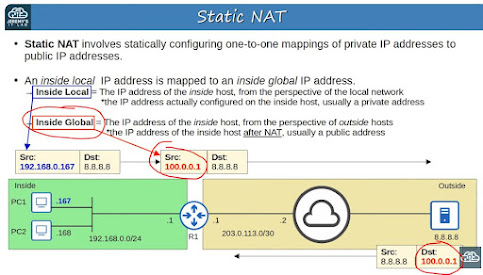
Configures static one-to-one mappings of private IP addresses to public IP addresses.

IP Address Terms:
- Inside Local = IP addr of the inside host from the perspective of the local network.  Ex)192.168.0.167
- Inside Global = The IP address of the inside host AFTER NAT.  Usually a public and routable IP address.

- Outside Local = IP address of outside host from the perspective of the local network.  Ex) 8.8.8.8
- Outside Global = IP address of the outside host from the perspective of the rest of the world.  Ex) Also 8.8.8.8

For our purposes these two addresses are usually the same for static NAT:
- Outside Local
- Outside Global


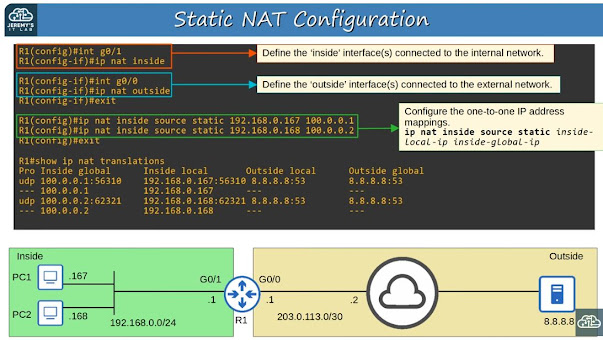
R1(config)#int g0/1
R1(config-if)#ip nat inside

R1(config)#int g0/0
R1(config-if)#ip nat outside
^ These two commands tell the router on which interfaces to enable NAT.  One inside (internal), one outside (external).

R1(config)#ip nat inside source static <inside-local-ip-addr> <inside-global-ip-addr>
^ This configures the mapping of the internal IP address to the publicly routable external IP address.


Note that at first blush this makes static NAT seem useless because it still requires the same number of public routable IP addresses.  It's not NAT behind a firewall like what we're used to.  However, it truly provides NAT services - it "hides" the internal IP from the external world.  It's just that each private internal IP address has to have an extra external IP address that it can use for Internet purposes.

Examples:
R1(config)#ip nat inside source static 192.168.0.167 100.0.0.1
R1(config)#ip nat inside source static 192.168.0.168 100.0.0.2


R1#ip nat translations
^ Shows what mappings exist and how they are being used.  Look for port numbers on active "in use" IP addresses.


R1#ip nat statistics
^ Displays info about NAT such as how many NAT mappings have been defined, how many are dynamically in use, and which interfaces are confgured for static NAT.

R1#clear ip nat translation *
^ This clears all the dynamic (in flight) used NAT translations.  (The mappings with port numbers will be removed).


[These are my notes from Jeremy's excellent CCNA course which can be viewed here.] 


Monday, June 3, 2024

Cisco 127 - SSH and Telnet

Console Port Security:

By default, no password is needed when accessing via console port.
You can configure a password on the console line:

R1(config)#line console 0
^There is only one line, so number is always 0

R1(config-line)#password ccna
^Set the password

R1(conifg-line)#login
^Tells the device to require the password on the line

Alternative: Tell device to require usernames instead of a shared password

R1(config)#username smith secret Sammywich
^Creates a user named 'smith' with password 'Sammywich'

R1(config)#line console 0
^Same as previous config, switch over to the console line

R1(config-line)#login local
^Configure device to require a username to gain entry

Assign an IP address to a Layer-2 switch:

Q) Since switches are layer 2, how can we SSH to them?
A) Create a switch virtual interface (SVI) and assign the SVI an IP address.  You'll also need to define a default gateway.

SW1(config)#interface vlan1
^Define the SVI
SW1(config-if)#ip address 192.168.1.253 255.255.255.0
^Assign an IP address to the SVI
SW1(config-if)#no shutdown
^Turn on the interface
SW1(config-if)#exit

SW1(config)#ip default-gateway 192.168.1.254
^Configure a default gateway for the switch

Telnet Config:


We are unlikely to enable telnet, but we can learn from looking at it

SW1(config)#enable secret ccna
^Require a password to access privileged exec mode. If we don't do this, we can't get to it via Telnet/SSH.

SW1(config)#username smith secret Sammywich
^Define a local username

SW1(config)#access-list 1 permit host 192.168.2.1
^Create an access-list that we can later assign to a telnet line so we can restrict it to allow incoming connections from a single IP address

SW1(config)#line vty 0 15
^Instead of configuring a single console line, this time we are configuring Virtual TeleType lines 0 through 15 (all of them).

SW1(config-line)#login local
^Require the use of locally defined usernames

SW1(config-line)#exec-timeout 5 0
^Define an inactivity timer of 5 minutes 0 seconds. After this, your session gets disconnected.

SW1(config-line)#transport input telnet
^Restrict these lines to telnet only.  No SSH or RLogin.
Other options:
transport input telnet - Only Telnet
transport input ssh - Only SSH
transport input telnet ssh - Both
transport input all - All connections (including telnet, SSH, Rlogin, and more)
transport input none - Nope, nada

SW1(config-line)#access-class 1 in
^Similar to Standard ACLs, this assigns the access list previously defined about a dozen lines up to these lines on incoming sessions.

SSH Config:

Use v2, not v1.
"v1.99" = Supports both v1 and v2
Telnet = TCP port 23
SSH = TCP port 22

You will need an RSA key of at least 768 bits for SSH v2.

Before proceeding, define the hostname and domain name.

Switch>en
Switch#conf t
Switch(config)#hostname SW1
^Configure the device's hostname

SW1(config)#ip domain name jeremysitlab.com
^Configure the device's domain name

SW1(config)#crypto key generate rsa
^This generates the RSA public and private key pair that you will need later.  Jeremy uses 2048 as the number of bits int he modulus.  Don't fall for the [512] default because we know it needs to at least be 768.
Instead of interactively choosing the modulus length, maybe use this command:
SW1(config)#crypto key generate rsa modulus 2048

(Some countries may need to use smaller modulus lengths due to USA's encryption laws.)

Next 3 commands are the same as Telnet was (above) (except I'll replace "Telnet" with "SSH":

SW1(config)#enable secret ccna
^Require a password to access privileged exec mode. If we don't do this, we can't get to it via Telnet/SSH.

SW1(config)#username smith secret Sammywich
^Define a local username

SW1(config)#access-list 1 permit host 192.168.2.1
^Create an access-list that we can later assign to an ssh line so we can restrict it to allow incoming connections from a single IP address

SW1(config)#ip ssh version 2
^Configure for SSH v2

Next 5 commands are same as Telnet (except for SSH):

SW1(config)#line vty 0 15
^Instead of configuring a single console line, this time we are configuring Virtual TeleType lines 0 through 15 (all of them).

SW1(config-line)#login local
^Require the use of locally defined usernames

SW1(config-line)#exec-timeout 5 0
^Define an inactivity timer of 5 minutes 0 seconds. After this, your session gets disconnected.

SW1(config-line)#transport input ssh
^Restrict these lines to ssh only (no telnet).

SW1(config-line)#access-class 1 in
^Similar to Standard ACLs, this assigns the access list previously defined about a dozen lines up to these lines on incoming sessions.


[These are my notes from Jeremy's excellent CCNA course which can be viewed here.]


Cisco 126 - Syslog

R1(config)#logging console <severity>
^ Sets the level at which messages will be displayed, from <severity> up to and including 0.  So, by specifying "6" (Informational), levels 0 through 6 will be displayed on the console.
Enabled by default at level 7.

Level = Keyword
0 = Emergency
1 = Alert
2 = Critical
3 = Error
4 = Warning
5 = Notice
6 = Informational
7 = Debugging

Mnemonic aid:
Every Awesome Cisco Enginer Will Need Ice cream Daily

R1(config)#logging monitor <severity>
^ Displays syslog messages on ssh/telnet

R1(config)#logging buffered [size] <severity>
^ Stores syslog messages in buffer (memory).  Size = buffer size in bytes.  Bigger number = bigger log but takes away space from operating memory.

R1(config)#logging <server-ip>
R1(config)#logging host <server-ip>
^ These two commands are the same.  Configures device to send syslog messages to external central server which can collect logs from multiple devices for later analysis.

R1(config)#logging trap <severity>
^ Sets the level that will be sent to the external server.

R1(config)#terminal monitor
^ Syslog messages won't be displayed via Telnet/SSH unless you tell them to with this command.

R1(config)#logging synchronous
^ Displays syslog messages on their own line, not in the middle of my console entries.

R1(config)#service timestamps [datetime | uptime]
^ Controls whether syslog entries are displayed with date and time vs. system uptime.

R1(config)#service timestamps log datetime
R1(config)#service sequence-numbers
^ These two commands tell the device to display both date and sequence number in syslog messages.


[These are my notes from Jeremy's excellent CCNA course which can be viewed here.]

Cisco 125 - SNMP

R1(config)#snmp-server contact admin@MyCompany.com
R1(config)#snmp-server location IT Suite Lab A
^Set contact info & location of device

R1(config)#community MyPassword1 ro
R1(config)#community MyPassword2 rw
^ Sets the community strings (passwords) for read only and read/write

R1(config)#snmp-server host 192.168.1.1 version 2c WhoDat1
^ Configures the IP address of the NMS, SNMP version, and which community string to use with this server

R1(config)#snmp-server enable traps snmp linkdown linkup
R1(config)#snmp-server enable traps config
^ Set linkdown/up traps and configuration traps to the NMS monitor


[These are my notes from Jeremy's excellent CCNA course which can be viewed here.]

Friday, May 31, 2024

Cisco 124 - DHCP

DHCP D-O-R-A


Discover    Client --> Server    Broadcast
Offer        Server --> Client    Broadcast or Unicast
Request        Client --> Server    Broadcast
Ack            Server --> Client    Broadcast or Unicast


R1(config-if)#ip helper-address <ip-addr>
^ Configures router as a DHCP relay agent.
Notice that you are on a specific interface when you do this.

R1(config-if)#ip address dhcp
^ Configures router as a DHCP client (umm... rare.)
Again, notice you are on a specific interface when you do this.

To config router as a DHCP server:


R1(config)#ip dhcp excluded-address low-address high-address
^ Cisco is weird.  You start by defining addresses you want to *exclude* from the range of available addresses.  I guess the idea is that it just automatically hands all the addresses on a subnet out unless you exclude them.

Ohhhh... I guess this is because we don't actually activate the lease.  I'll bet it's live as soon as it is defined.  So you have to first exclude the range before you create it.

R1(config)#ip dhcp pool <pool-name>
^Define a pool-name like LAB_POOL

R1(config)#network <ip-address> {/prefix-length | subnet-mask}
^This carves out a range of IP addresses to hand out (minus the ones that were excluded)

R1(config)#dns-server <ip-address>
^Config the scope for a specific DNS server.

R1(config)#domain-name <domain-name>
^Config scope with a domain name like jeremy.com

R1(config)#default-router <ip-address>
^Config scope for a specific default router

R1(config)#lease {days hours minutes | infinite}
^Define the lease length


[These are my notes from Jeremy's excellent CCNA course which can be viewed here.]

Cisco 123 - DNS

To configure a router as a DNS server:
R1(config)#ip dns server

Add host entries:
R1(config)#ip host R1 192.168.0.1
R1(config)#ip host PC1 192.168.0.101
R1(config)#ip host PC2 192.168.0.102
R1(config)#ip host PC3 192.168.0.103

Configure an external DNS server that R1 can use if requested record is not in local host table on router:
R1(config)#ip name-server 8.8.8.8

R1(config)#ip domain lookup
^Enabled by default, this enables the router to do DNS lookups

R1#show hosts
^ Displays configured hosts and those learned through look-ups of external DNS

Flags:
perm = Configured on router
temp = Cached in local router due to external lookup

To configure a router as a DNS client:
R1(config)#ip name-server 8.8.8.8
R1(config)#ip domain lookup

To configure the default domain name of a router:
R1(config)#ip domain name yourname.com


[These are my notes from Jeremy's excellent CCNA course which can be viewed here.]

Thursday, May 30, 2024

Cisco 122 - NTP

Network Time Protocol

R1#show clock
^Display the time and date

R2#clock set hh:mm:ss DayOfMonth Month Year
^ Set clock

clock = Software clock
calendar = Hardware clock

R2#calendar set hh:mm:ss DayOfMonth Month Year
^ Set hardware clock

R2#show calendar
^ Display hardware clock time & date

R2(config)#clock timezone EST 4
^ Set software clock timezone.
EST = Time zone name
4 = Hour offset from UTC

R2(config)#clock summer-time EDT <date|recurring>
^ Set Daylight Savings Time
Date = When to start
Recurring = Set up a yearly schedule

R1(config)#clock summer-time EDT recurring 2 Sunday March 02:00 1 Sunday November 02:00
^ The first date is when DST starts;
the second is when DST ends

R1(config)#ntp server ip-address [prefer]
^ Tells the router which NTP server from which it should get time

R1(config)#ntp peer ip-address
^ Devices can peer with one another at the same stratum to provide more accurate time
Devices peering with another device is called 'symmetric active'
Modes:
- Server mode
- Client mode
- Symmetric active mode (peer)

NTP does not update the hardware calendar clock.  

R1(config)#ntp update-calendar
^ This will update the hardware calendar clock with the NTP provided time

R1(config)#ntp master [stratum]
^Sets the device as a master clock

R1(config)#source interface
^Tells R1 to use <interface> as the soruce of its NTP messages (when acting as a server)
Example:
R1(config)#interface loopback0
R1(config-if)#ip address 10.1.1.1 255.255.255.255
R1(config-if)#exit
R1(config)#ntp source loopback0

R1#show ntp associations
^Displays which NTP servers the device pulls time from

R1#show ntp status
^Displays additional info

There is some errata at Jeremy's lab that indicates the following authentication stuff is not needed unless using ntp passive, broadcast, or multicast stuff:

R1(config)#ntp authenticate
^ Enable NTP authentication

R1(config)#ntp authentication-key <key-number> md5 <key>
^ Create NTP authentication keys

R1(config)#ntp trusted-key <key-number>
Specify the trusted key(s)

R2(config)#ntp <ip-address> key <key-number>
^Notice this isn't needed on R1.
Used on R2, this command specifies which key is needed when pulling time from <ip-address>


[These are my notes from Jeremy's excellent CCNA course which can be viewed here.]

Wednesday, May 29, 2024

Cisco 121 - CDP & LLDP

CDP = Cisco Discovery Protocol
LLDP = Link Layer Discovery Protocol

CDP is Cisco proprietary.
LLDP came later and is industry standard.

They are very similar and do the same things.  They are Layer 2 (Ethernet) discovery protocols that share info and discover info about neighboring (connected) devices.

CDP:

Enabled by default.
Both globally and on each interface.

Sent to MAC 0100.0CCC.CCCC
Devices don't forward CCDP frames.
By default sent every 60 seconds.
Holdtime = 180 seconds.  If no updates within 180 seconds, remove the neighbor from the CDP neighbor table.
Default is CDPv2.

R1#show cdp
^Displays basic info about CDP (timers, version)

R1#show cdp traffic
^Shows how many CDP messages sent/received

R1#show cdp interface
^Displays which interfaces CDP is enabled on

R1#show cdp neighbors
^Lists neighbors and some basic info on each

R1#show cdp neighbors detail
^More details

R1#show cdp entry <name>
^Same info as above but for specified neighbor

R1(config)#[no] cdp run
^Disable or enable CDP on device

R1(config-if)#[no] cdp enable
^Disable or enable CDP on specific interface.
Recall by default CDP is enabled globally (on the device) and on each interface.

R1(config)#cdp timer <seconds>
Recall default is 60

R1(config)#cdp holdtime <seconds>
Recall default is 180 seconds after which neighbor is removed from CDP neighbor table

R1(config)#[no] cdp advertise-v2
Disable/enable CDP v2.
If v2 is disabled, device will use v1.


LLDP:

Disabled by default.
Must be manually enabled on Cisco devices.
You can run both CDP and LLDP simultaneously.
Sent to MAC C180.C200.000E

Sent every 30 seconds. (CDP is 60)
Holdtime is 120 seconds. (CDP is 180)

Reinitialization delay - Delays the actual initialization of LLDP on an interface by 2 seconds by default.

R1(config)#lldp run
^ Enables LLDP

R1(config-if)#lldp transmit
R1(config-if)#lldp lldp receive
^ Must turn on both transmit and receive on each interface.

R1(config)#lldp timer <seconds>
R1(config)#lldp holdtime <seconds>
R1(config)#lldp reinit <seconds>


[These are my notes from Jeremy's excellent CCNA course which can be viewed here.]


Tuesday, May 28, 2024

Cisco 120 - Extended ACLs

Extended ACLs are like Standard ACLs but you can filter by source/destination IP, protocol, port, and other stuff.

Since they are more surgical/precise, the recommendation is to place them close to the source instead of the destination like with Standard ACLs.  This is because Standard ACLs tend to sweep up too much stuff, whereas Extended ACLs can pinpoint very specific traffic, prevent it from entering the network (think WANs), and save traffic.

Standard ACLs use numbers 1-99 and 1300-1999
Extended ACLs use numbers 100-199 and 2000-2699

Syntax:
R1(config)#access-list number [permit | deny] protocol src-ip dest-ip

R1(config)#ip access-list extended {name | number}
R1(config-ext-nacl)#[seq-num] [permit|deny] protocol src-ip dest-ip

Example:
R1(config-ext-nacl)#deny tcp any 10.0.0.0 0.0.0.255
^ Blocks all packets from any source to any host in 10.0.0.0/24

R1(config-ext-nacl)#permit ip any any
^ Allow anything.

R1(config-ext-nacl)#deny udp 10.0.0.0 0.0.255.255 host 192.168.1.1
^ Prevent 10.0.0.0/16 from sending UDP traffic to 192.168.1.1/32

R1(config-ext-nacl)#deny icmp host 172.16.1.1 192.168.0.0 0.0.0.255
^ Deny pings from 172.16.1.1/32 to 192.168.0.0/24

You can also do specific ports:

R1(config-ext-nacl)#deny tcp src-ip ___ src-port-num dest-ip

The blank can be:
eq 80 = equals 80
gt 80 = greater than 80 (81 and higher)
lt 80 = less than 80 (79 and less)
neq 80 = not equal 80
range 80 100 = from port 80 to 100

Example:
R1(config-std-nacl)#deny tcp any host 1.1.1.1 eq 80
^ Deny all packets destind for IP 1.1.1.1/32 on TCP port 80 (web)

R1(config-std-nacl)#permit tcp 172.16.1.0 0.0.0.255 gt 9999 host 4.4.4.4 neq 23
^ Allow hosts in 172.16.1.0/24 using TCP source port greater than 9999 to access all TCP ports on 4.4.4.4 except port 23

R1#show access-lists
^ Will display configured ACLs

R1#show ip interface g0/0
^ Shows details about int g0/0 including outgoing and inbound access lists

!! Easy to forget !!
Now apply the ACL to an interface:
R1(config-if)#ip access-group number {in|out}


[These are my notes from Jeremy's excellent CCNA course which can be viewed here.]

Monday, May 27, 2024

Cisco 119 - Standard ACLs

ACL = Access Control List
ACE = Access Control Entry

A single ACL contains multiple sequentially ordered ACEs

ACLs = Like simple IP-based firewall rules (source/destination).

ACLs are configured globally on the router and then applied to an inbound or outbound interface.

Implicit DENY ALL at the end.  After finding the first match, the router won't process remaining ACEs.


ACL Types:
Standard - Match based on source IP address only
    - Standard Numbered ACLs
    - Standard Named ACLs

Extended ACLs - Match based on Source/Destination IP, Source/Dest port, etc.
    - Extended Numbered ACLs
    - Extended Named ACLs

Standard ACLs use numbers 1-99 and 1300-1999.

Standard Numbered ACLs:

Syntax:
R1(config)#access-list number {deny | permit } ip wildcard-mask

R1(config)#access-list 1 deny 1.1.1.1 0.0.0.0
R1(config)#access-list 1 deny 1.1.1.1
^ These both do the same thing.  Deny a specific host at 1.1.1.1
R1(config)#access-list 1 deny host 1.1.1.1
^ Same as previous two. Historical.

R1(config)#access-list 1 permit any
R1(config)#access-list 1 permit 0.0.0.0 255.255.255.255
^ These both do the same thing: allow all.
R1(config)#access-list 1 remark ## My comment goes here ##
^ Comments

Here is an example access list:
R1(config)#access-list 1 deny 1.1.1.1 0.0.0.0
R1(config)#access-list 1 permit 0.0.0.0 255.255.255.255
R1(config)#access-list 1 remark ## Block Bob from Accounting ##

R1(config)#do show access-lists
Standard IP access list 1
    10 deny 1.1.1.1
    20 permit any

^ Notice there could have been other types of access lists.

R1(config)#do show ip access-lists
Standard IP access list 1
    10 deny 1.1.1.1
    20 permit any

^ This limits output to ONLY IP access-lists

R1(config)#do show running-config | include access-list
access-list 1 deny 1.1.1.1
access-list 1 permit any
access-list 1 remark ##Block Bob from Accounting ##

^ Notice how we had to coax comments out from the running-config

!! Easy to forget !!
Now apply the ACL to an interface:
R1(config-if)#ip access-group number {in|out}

Recommendation for Standard ACLs: Apply the ACL to the interface nearest the destination.

Standard Named ACLs:

Still only match based on source IP

R1(config)#ip access-list standard acl-name
R1(config-std-nacl)#[entry-number] {deny|permit} ip wildcard-mask

R1(config)#ip access-list standard BLOCK_BOB
R1(config-std-nacl)#5 deny 1.1.1.1
R1(config-std-nacl)#10 permit any
R1(config-std-nacl)#remark ## Configured May 27 2024 ##
R1(config-std-nacl)#int g0/0
R1(config-if)#ip access-group BLOCK_BOB in


Editing and resequencing ACLs

You can configure numbered ACLs the same way as named ACLs:

R1(config)#access-list 1 deny 192.168.1.1
R1(config)#access-list 1 permit any
^ The normal numbered way

R1(config)#ip access-list standard BLOCK_PC1
R1(config-std-nacl)#deny 192.168.1.1
R1(config-std-nacl)#permit any
^ The named way

R1(config)#ip access-list standard 1
R1(config-std-nacl)#deny 192.168.1.1
R1(config-std-nacl)#permit any
^ Use the numbered ACL as a name

With this approach, you can modify ACEs in an ACL:

R1(config-std-nacl)#no 30
^ This would remove ACE 30

R1(config-std-nacl)#30 deny 192.168.2.0 0.0.0.255
^ This would insert a new ACE 30 whereas we previously deleted it

We can also renumber (resequence) ACEs in an ACL:

R1(config)#ip access-list resequence 1 5 10
^ This would renumber ACL #1 starting at 5 and incrementing by 10
Probably more common to start at 10 and increment by 10:
R1(config)#ip access-list resequence 1 10 10


[These are my notes from Jeremy's excellent CCNA course which can be viewed here.]
Cisco 118 - IPv6 More

Solicited-Node Multicast Address:

ff02::0001:ff + Last 6 hex digits of unicast address

Example:
Unicast address: 2001:0db8:0000:0001:0f2a:4fff:fea3:00b1
-->
ff02::0001:ffa3:00b1
Shortened:
ff02::1:ffa3:b1

Neighbor Discover Protocol (NDP)
Replaces IPv4 ARP
Uses ICMPv6 and solicited-node multicast addresses to learn MAC address of other hosts.
NS = Neighbor Solicitation = ICMPv6 Type 135 = NDP equivalent of ARP Request
NA = Neighbor Advertisement = ICMPv6 Type 136 = NDP equivalent of ARP Reply

R1#show ipv6 neighbor
^ Shows the IPv6 Neighbor Table
This is the equivalent of IPv4 MAC Table
Displays:
IPv6 Address            Age    Link-Layer Addr    State    Interface
FE80::C802:9FF:FE7C:8    0    ca02.097c.0008    REACH    Gi0/0
2001:DB8::78:9ABC        0    ca02.097c.0008    REACH    Gi0/0

NDP also has a process to automatically discover routers on the local network:
RS = Router Solicitation = ICMPv6 Type 133
    Asks all routers on local link to identify themselves
    Sent when interface connects to network
    Sent to multicast address FF02::2 (all routers)
RA = Router Advertisement = ICMPv6 Type 134
    Router announces its presence and info about the link
    Sent in response to RS messages and periodically resent
    Sent to multicast address FF02::1 (all nodes)
    
Summary:
RS = Type 133 = Sent to FF02::2 (all routers)
RA = Type 134 = Replies to FF02::1 (all nodes)
NS = Type 135 = Sent to solicited-node multicast ff02::0001:ff + Last 6 hex
NA = Type 136 = Reply to NS

SLAAC
Stateless Address Auto-configuration
Automatically configures IPv6 addresses
Host uses RS/RA messages to learn IPv6 prefix of local link and then use EUI-64 to generate IPv6 address

R2(config-if)#ipv6 address prefix/prefix-length eui-64
^ This requires the prefix and prefix-length
vs
R2(config-if)#ipv6 address autoconfig
^ This uses SLAAC. No need to know prefix/length.

Duplicate Address Detection (DAD)
(Asks Dad if I can use this IPv6 address before I start using it.)
Uses NDP to see if anything else is using my configured IP address.
Host sends an NS using its own IP address.
If no reply, device knows the address is OK.  (Thanks, Dad.)
If device gets a NA reply, not OK.

IPv6 Static Routing
ipv6 route destination/prefix-length {next-hop | exit-interface [next-hop]} [ad]

Recall "ad" = Administrative Distance

Network route:
R1(config)#ipv6 route 2001:db8:0:3::/64 2001:db8:0:12::2
^ This is also a recursive route because the router will have to look up how to get to 2001:db8:0:12::2

Host route:
R2(config)#ipv6 route 2001:db8:0:1::100/128 2001:db8:0:12::1
R2(config)#ipv6 route 2001:db8:0:3::100/128 2001:db8:0:23::2
^ Notice with these two commands we specified the prefix length of /128.  
Each line is defining a very specific route to a specific host.

Default route:
R3(config)#ipv6 route ::/0 2001:db8:0:23::1
^ Like 0.0.0.0/0 in IPv4


[These are my notes from Jeremy's excellent CCNA course which can be viewed here.]


Sunday, May 26, 2024

Cisco 117 - IPv6 Continued

EUI-64

EUI = Extended Unique Identifier
Method of converting a 48-bit MAC address into the *host* portion of a /64 IPv6 address

1) Divide the MAC address in half:
1234 5678 90AB --> 1234 56 | 78 90AB

2) Insert FFFE in the middle:
1234 56FF | FE78 90AB

3) Invert the 7th bit:
1234 56FF FE78 90AB
 ^

Recall that each hexadecimal digit is 4 bits.
[Sidenote: I always forget each hex decimal is 4 bits.  Here's why:
Hexadecimal F = Decimal 15.
Decimal 15 = Binary 1111
Notice there are 4 bits (ones) in Binary 1111.
Decimal 1 = Binary 0001
Still 4 bits.]


So the 7th bit is "buried in" the second hex digit.
Hexadecimal 12 = binary 0001 0010
Invert the 7th bit in the second group:
0010 --> 0000
Now convert the result back to hexadecimal
Binary 0000 --> 0
So the EUI becomes:
1034 56FF FE78 90AB
 ^


Doing the math in my head is a pain so memorize this table:


Given this network prefix: 2001:db8::

R1(config)#int g0/0
R1(config-if)#ipv6 address 2001:db8::/64 eui-64
R1(config-if)no shutdown

^ This will tell the router's interface to use EUI-64 rules to configure the interface.


Two more examples:
R1(config-if)#int g0/1
R1(config-if)#ipv6 address 2001:db8:0:1::/64 eui-64
R1(config-if)no shutdown

R1(config-if)#int g0/2
R1(config-if)#ipv6 address 2001:db8:0:2::/64 eui-64
R1(config-if)no shutdown

R1#show interfaces g0/0
^This will reveal MAC address of g0/0

Types of IPv6 addresses:

- Global unicast
    Public address; can be used over Internet. Must be registered.
    Originally defined as 2000::/3 (2000:: to 3FFF....FF)
    Now defined as all addresses not otherwise reserved for other purposes
    Example:
    2001:0DB8:8B00:0001:0000:0000:0000:0001/64
    
    The first three groups are the 48-bit 'global routing prefix' assigned by the ISP:
    2001:0DB8:8B00
    
    The fourth group is the 16-bit subnet identifier:
    0001
    
    Together, they make up the 64-bit (/64) IPv6 network prefix.
    
    The remaining four groups make up the 64-bit 'interface identifier' -- the host portion of the address.
    16 hexadecimal digits = 16 digits x 4 bits each = 64 bits
    
- Unique local
    Private IPv6 addresses which cannot be used over the Internet.
    Like IPv4 10, 172, 192...
    Try to make the addresses unique in case your organization merges with another.
    Defined as:
    FC00::/7
    (FC00:: to FDFF....FF)
    Later update forced them all to start with FD.
    Example:
    FD45:93AC:8A8F:0001:0000:000:0000:0001/64
    
    FD says unique local address
    
    Next 40 bits (45:93AC:8A8F) should be randomly generated for merger reasons.
    
    Last 4 groups are the 64-bit interface identifier.
    
- Link local
    Automatically generated on IPv6 enabled devices.
    R1(config-if)#ipv6 enable
    ^ Enables IPv6 on an interface without actually assigning an IP address.
    Typically the interface gets a link local IPv6 address in addition to the one you assign; in this case, it would only have a link local IPv6 address.
    Defined as:
    FE80::/10
    (FE80:: to FEBF:FFFF.....FF)
    However standard has a wrinkle that restricts them to begin with FE8.
    Interface ID is generated using EUI-64 rules.
    Link local = Used for communication within a single link (subnet).
    Routers will not forward packets with link-local destination IPv6 addresses.
    Commonly used for routing protocol peerings (OSPFv3) and next-hop address for static routes.
    
- Multicast
    Unicast addresses are 1-to-1
    Broadcast is from one source to all destinations
    Multicast is 1 to many destinations
    Defined as:
    FF00::/8
    (FF00:: to FFFF....FFFF)
    IPv6 does not broadcast like IPv4.
    But it has a multicast to all hosts in subnet that is like a broadcast.
    Common multicast addresses:


    Multicast address scope = How far multicast scope should be forwarded.
    FF01 = Interface-local (127.0.0.1 -- Stay on local device)
    FF02 = Link-local = Local subnet - Routers won't forward between subnets
    FF05 = Site-local - Limited to a single physical location (like a LAN).  Not forwarded over a WAN.  Defined by SysAdmin.
    FF08 = Organization-local - An entire company.
    FF0E = No boundaries. Can be routed over Internet.
    
- Anycast
    "One to one of many"
    Whereas multicast is one to all in that group (one to many), anycast is one to any one of multiple in a group.
    For example, multiple routers might be configured with the same IPv6 address.  The "nearest" (by routing metric) would receive the anycast.
    No specified range.
    R1(config-if)#ipv6 address 2001:db8:1:1::99/128 anycast
    ^ This assigns an IPv6 address to an interface and tells the interface it is an "anycast" address.  The /128 is like an IPv4 /32.
    
- Other IPv6 Addresses
    :: = Unspecified (such as when a device does not yet know its IPv6 address). IPv4 equivalent = 0.0.0.0
    ::1 = Loopback address (like 127.0.0.1/8)
    
Summary:
    FC & FD = Unique local = Private IP
    FE8 = Link local = Local subnet
    FF = Multicast
        FF01 = Interface-local (127.0.0.1)
        FF02 = Link-local = Local subnet - Routers don't route
        FF05 = Site-local = Single physical location like a LAN
        FF08 = Organization-local = An entire company
        FF0E = No boundaries. Can be routed over Internet.


[These are my notes from Jeremy's excellent CCNA course which can be viewed here.]

Saturday, May 25, 2024

Cisco 116 - IPv6 Intro

 R1(config)#ipv6 unicast-routing
^ Enable routing for IPv6

R1(config)#int g0/0
R1(config-if)#ipv6 address 2001:db8:0:0::1/64
R1(config-if)#no shutdown
^ Assign an IPv6 address to interface g0/0

R1#show ipv6 interface brief
GigabitEthernet0/0 [up/up]
    FE80::EF8:22FF:FE36:8500
    2001:DB8::1

Notice two IPv6 addresses were assigned.
The first FE80 address is an automatically assigned Link-Local address.
The second 2001 address is the one I assigned.


[These are my notes from Jeremy's excellent CCNA course which can be viewed here.]


Saturday, May 11, 2024

Cisco 115 - OSPF Part 3

R5#show ospf interface g0/0
^ Displays info about OSPF on interface g0/0

R2(config)#int g0/0
R2(config-if)#ip ospf priority 255
^ Sets the priority of OSPF on an interface to "rig" future elections.  Recall that the DR/BDR election is 'non-preemptive'.

DR = Designated Router
BDR = Backup Designated Router

R5#clear ip ospf process
^ Don't do this in a production network.
Forces an election.  When the DR goes down, the current BDR will become the DR.  Then, an election will occur and this rigged router will become the BDR.  I guess the next election will cause this router to become the DR.

R5#show ip ospf neighbor
^ Displays info about OSPF neighbors and their state

 R3#show ip ospf interface brief
^ Displays interfaces and OSPF info for each

R3#show ip ospf interface g0/0
^ Displays detailed OSPF info on interface g0/0

Serial interfaces:
- DR and BDR are not elected because there are only 2 neighbors on the interface
- One side functions as DCE (Data Communications Equipment)
- The other side functions as DTE (Data Terminal Equipment)
- DCE needs to specify clock rate (speed) of connection

R1(config-if)#clock rate 64000
^ Sets the clock rate (bps) of the DCE router
R1(config-if)#ip address 192.168.1.1 255.255.255.0
R1(config-if)#no shut

Ethernet interfaces use the speed command.
Serial interfaces use the clock rate command.

Default encapsulation on serial interface is HDLC

R1(config)#int s2/0
R1(config-if)#encapsulation ppp
^ Sets encapsulation to PPP instead of the default HDLC
Encapsulation type must match on both ends.

R1#show controllers s2/0
^ This will reveal which side is the DCE vs the DTE

R1(config-if)#ip ospf network <type>
^ This command manually configures the OSPF network type with the following <type> options:
broadcast (Ethernet and FDDI)
non-broadcast (Frame Relay and X.25)
point-to-point (Serial)
point-to-multipoint

You might configure an Ethernet link between two routers since there is no need for a DR/BDR.  This might be a time to config a point-to-point network.

R2(config-router)#router-id 1.2.3.4
^ Configures the router-id of a router

The hello-interval and dead-interval values must match between OSPF neighbors:

R2(config-if)#ip ospf hello-interval <seconds>
^ Sets the number of seconds between hello announcements
Default is 10 seconds

R2(config-if)#ip ospf dead-interval <seconds>
^ Sets how long before the neighbor is considered dead
Default is 40 seconds

R2(config-if)#ip ospf authentication-key banana
^ Sets the authentication password to banana but does not yet enable authentication
R2(config-if)#ip ospf authentication
^ Enables authentication on the interface

R2(config-if)#ip mtu <number>
^ Sets the maximum size of an IP packet that can be sent ot of the interface. Defaults to 1500 bytes.
Must match on both neighbors or will have problems.

OSPF LSA types:
Type 1 - Router LSA - Identifies itself by stating its router ID and lists networks attached to the router's OSPF attached interfaces.
Type 2 - Network LSA - Generated by the DR of each 'multi-access' (broadcast) network. Lists the routers which are attached to the multi-access network.
Type 5 - AS-External LSA - Generated by ASBRs (Autonomous System Boundary Routers) to describe routes to destinations outside of the AS (Autonomous System) (OSPF domain)

R1#show ip ospf database
^ Displays LSDB (OSPF database) including neighbors, each router (type 1 LSA), network (type 2) LSA, and external link states (type 5)


 OSPF Neighbor process:


[These are my notes from Jeremy's excellent CCNA course which can be viewed here.]


Friday, May 10, 2024

Cisco 114 - OSPF Part 2

R3#show ip ospf interface f2/0
^ Displays OSPF info about interface f2/0. Includes cost info.

R3(config-router)#auto-cost reference-bandwidth <mbps>
^ Sets the reference bandwidth for better cost calculations.
The default reference bandwidth is 100 mbps which is the speed of Fast Ethernet.
On all your routers, set the reference-bandwidth to higher than your highest link.  This allows for later growth.

R1(config)#int g0/0
R1(config-if)#ip ospf cost 10000
^ Manually sets the ospf cost of an interface to 10000

Not recommended:
Another way to change the OSPF cost of an interface is with the bandwidth command.  Recall the formula to calculate OSPF cost is:
reference bandwidth / interface bandwidth

R1(config-if)#bandwidth <kbps>
^The interface speed does not actually change, but costs calculated with OSPF metrics use the bandwidth number.

R3#show ip ospf interface brief
^ Displays OSPF costs for each interface

R1#show ospf neighbor
^ Displays info about ospf neighbors

R1(config)#int g0/0
R1(config-if)#ip ospf 1 area 0
R1(config-if)#int g1/0
R1(config-if)#ip ospf 1 area 0
^ These commands specifically go into two interfaces and activates OSPF on them

R1(config-router)#passive-interface default
^ Configure ALL interfaces as OSPF passive interfaces

R1(config-router)#no passive-interface <int-id>
^ Turns off passive interface for specified interface

show ip protocols
^ Displays OSPF info


[These are my notes from Jeremy's excellent CCNA course which can be viewed here.]

Friday, May 3, 2024

Cisco 113 - OSPF Part 1

(config)#router ospf 1
^ Enters OSPF configuration mode.
The "1" is the process ID.
A router can run multiple OSPF processes at once.
Process ID is unrelated to area.

(config-router)#network 10.0.12.0 0.0.0.3 area 0
(config-router)#network 10.0.13.0 0.0.0.3 area 0
(config-router)#network 172.16.1.0 0.0.0.15 area 0
^ These three commands activate OSPF on all interfaces that match the given parameters.  They are configured as area 0.
The commands tell the router to find all interfaces that match the ranges specified.
Recall the network command uses wildcard matching.  So 0.0.0.15 = 255.255.255.240
Also recall that these commands don't specify which networks to advertise.
The commands activate OSPF on interfaces that fall in the range of the given wildcard matching patterns.

(config-router)#passive-interface g2/0
^ Tells the interface to stop sending OSPF 'hello' messages out that interface - probably because there are no further routers for that interface to neighbor with.
Use this command on any interface that doesn't have any OSPF neighbors.

(config)#ip route 0.0.0.0 0.0.0.0 203.0.113.2
^ Adds a default route and points to the next hop as the ISP's IP address
(This becomes our gateway of last resort)

(config-router)#default-information originate
^ This advertises the default route into OSPF so the other routers learn about it

R1#show ip protocols
^ Displays information about the routing protocol being used.
For us, that's OSPF

(config-router)#router-id 1.1.1.1
^ Manually configure the router ID as 1.1.1.1
The router will continue to use the old ID until we reload the router or use the command:
clear ip ospf process
^ Dangerous command because it clears out the routing map for a while until things are rebuilt.  This means downtime.

(config-router)#maximum-paths <#>
^ Change the maximum number of redundant paths that can be added to the routing table from 4 to #

(config-router)#distance <#>
^ Set the administrative distance

R4(config)#int l0
^ That's "L" 0 <-- Loopback0 (not the number 10)
This command creates a loopback interface
R4(config-if)#ip address 1.1.1.1 255.255.255.255
^ Assigns IP address 1.1.1.1/24 to interface Loopback0

R4>show ip int | begin Loop
^ Displays IP addresses assigned to interfaces beginning with the first match of "Loop" (Loopback0)

R4>show ip int brief
Shows a summary of interfaces and their IP assigned IP addresses

R4>show int l0
^ Again, that's loopback0, not the number 10
^ Command shows details of interface Loopback0

R1#show ip ospf neighbor
^ Shows OSPF neighbors

R1#show ip ospf database
^ Shows LSDB (link-state database)

R1#show ip ospf interface
^ Displays details about OSPF settings on each interface


[These are my notes from Jeremy's excellent CCNA course which can be viewed here.]

Tuesday, April 23, 2024

Cisco 112 - Trick for searching output: BEGIN

I miss piping output to 'less'

Ex)

show running-config | less

^ Does not work

My co-worker gave me this tip:

show running-config | begin ASDF

Shows the output from the running-config but starts ("begins") it at search string ASDF

Looks like it might accept regular expressions, too.  So:

show running-config | begin Gi2\/0\/3

Would begin output at Gi2/0/3


Friday, April 19, 2024

Cisco 111 - Dynamic Routes and Floating Static Routes

Administrative Distance costs

Administrative Distance <-- Route protocol/type
0 <-- Directly connected
1 <-- Static
20 <-- External BGP (eBGP)
90 <--  EIGRP
100 <-- IGRP
110 <-- OSPF
115 <-- IS-IS
120 <-- RIP
170 <-- EIGRP (external)
200 <-- Internal BGP (iBGP)
255 <-- Unusable route

Floating Static Routes

This is useful to configure a backup route that should not be used unless the normal path goes down.

#show ip route
^
Displays existing routes

(config)#ip route <network> <subnet> <ip of alternate next hop> <metric higher than usual path>
(config)#ip route 10.0.2.0 255.255.255.0 203.0.113.1 111

#show ip route
^You won't see the new route because its administrative cost is higher than the better path

Here's a way:
#show running-config | incl route

[These are my notes from Jeremy's excellent CCNA course which can be viewed here.]

Tuesday, April 16, 2024

Cisco 110 - EtherChannel

Conceptually, EtherChannel combines (aggregates) multiple linked ports into a single aggregate connection.

#show etherchannel load-balance
^Displays current load balancing method

#conf t
(config)#port-channel load-balance <mode>
(config)#port-channel load-balance src-dst-mac
(conifg)#show etherchannel load-balance
^
Change load balancing method to load balance based on source and destination IP address


Modes:
dst-ip    Destination IP address
dst-mac    Destination MAC address
src-dst-ip    Source & destination IP address
src-dst-mac    Source & destination MAC address
src-ip    Source IP address
src-mac    Source MAC address

Methods to create an EtherChannel:
1) Static = Manual config
    Don't do this because you want the switch to automatically remove a link when it goes down
2) Dynamic = Automatic
    A) PAgP (Port Aggregation Protocol) = Cisco proprietary
    B) LACP (Link Aggregation Control Protocol) = IEEE standard and preferred

(config)#interface range g0/0 - 3
(config-if-range)#channel-group 1 mode desirable
modes:
active = Enable LACP unconditionally
passive = Enable LACP only if a LACP device is detected
auto = Enable PAgP only if a PAgP device is detected
desirable = Enable PAgP unconditionally
on = Enable etherchannel only

For PAgP:
auto + auto = No EtherChannel
desirable + auto = EtherChannel
desirable + desirable = EtherChannel

For LACP:
passive + passive = No EtherChannel
active + passive = EtherChannel
active + active = EtherChannel

To config the aggregate etherchannel as a VLAN trunk, do this on both switches:
(config)#interface port-channel 1
(config-if)#switchport trunk encapsulation dot1q
(config-if)#switchport mode trunk
(config-if)#do show interfaces trunk

#show etherchannel summary
^
Displays port aggregates, protocol, and which ports are being used in each

#show etherchannel port-channel
^
Displays more details including the channel group mode

Layer 3 EtherChannel
(config)#int range g0/0 - 3
(conifg-if-range)#no switchport
(conifg-if-range)#channel group 1 mode active
(config-if-range)#int po1
(config-if)#ip address 10.0.0.1 255.255.255.252


[These are my notes from Jeremy's excellent CCNA course which can be viewed here.]

Saturday, April 13, 2024

Cisco 109 - Rapid Spanning Tree Protocol

SW3(config)#spanning-tree mode ?
mst    - Multiple Spanning Tree mode
pvst    - Per-Vlan Spanning Tree mode (classic mode)
rapid-pvst    - Rapid Per Vlan Spanning Tree mode (new & improved)

SW3(config)#spanning-tree mode rapid-pvst
^This is the default and we probably won't need to execute this.

SW1(config-if)#spanning-tree portfast
^
This command will tell a port it is connected to a PC or end host, not a switch or a hub.  Because there is no risk of creating a loop, they can move straight to the forwarding state without the negotiation process.  The port is the "edge" of the network, so they are called "edge ports".  They function like a classic STP port with PortFast enabled.

SW4(config-if)#spanning-tree link-type point-to-point
^This command tells the port it is connected to a switch

Costs:

Speed - STP Cost - RSTP Cost

10 Mbps - 100 - 2,000,000
100 Mbps - 19 - 200,000
1 Gbps - 4 - 20,000
10 Gbps - 2 - 2,000
100 Gbps - X - 200
1 Tbps - X - 20


[These are my notes from Jeremy's excellent CCNA course which can be viewed here.]

Friday, April 12, 2024

Cisco 108 - Spanning Tree Protocol

This is the feature that prevents infinite layer 2 loops among redundant links leading to broadcast storms.

SW3#show spanning-tree
VLAN0001


^Show who the root bridge is, this switch/bridge's priority, root status, role (designated, non-designated), and port cost for each interface.


SW3#show spanning-tree vlan 1
^Filter the output to only show vlan 1

SW3#show spanning-tree detail
Reveal
more details

Shorter overall view but displays number of ports in various states:
SW3#show spanning-tree summary
NAME    Blocking    Listening    Learning    Forwarding    STP Active
VLAN0001    0        0            0            4            4

Portfast is a feature that lets a a switch interface skip the listening/learning stages and go straight to forwarding state.  The idea here is that the interface is connected to a PC, not a switch.  If it isn't connected to a switch, there is no danger of a layer 2 infinite loop.

[Seems risky]


SW1(config-if)#spanning-tree portfast
^Enables portfast

SW1(config)#spanning-tree portfast default
^Enables portfast on all access ports by default

BPDU Guard makes this less risky.  If an interface enabled with BPDU guard receives a BPDU from another switch, the interface will be shut down to prevent a loop from forming:

SW1(config)#int g0/2
SW1(config-if)#spanning-tree bpduguard enable
^Turns on BPDU guard for a single interface

SW1(config)#spanning-tree portfast bpduguard default
^Turns on BPDU guard by default

SW1(config)#spanning-tree mode ?
^
Configures which spanning-tree mode the switch uses:
mst     Multiple spanning tree mode
pvst     Per-Vlan spanning tree mode (Classic with Cisco's per Vlan addition)
rapid-pvst     Per-vlan rapid spanning tree mode (Modern and improved per-Vlan spanning tree mode)

Rig a specific switch to act as the root bridge for vlan 1:

SW3(config)#spanning-tree vlan 1 root primary
^This command figures out the next lower priority (4096 less) for you so you don't have to calculate it.

SW2(config)#spanning-tree vlan 1 root secondary
^
Rig up a specific switch to act as a secondary.

Spanning Tree Costs:
STP - Cost    
10 Mbps - 100
100 Mbps - 19
1 Gbps - 4
10 Gbps - 2


[These are my notes from Jeremy's excellent CCNA course which can be viewed here.]


Sunday, April 7, 2024

Cisco 107 - Inter-VLAN Routing via SVI (Switch Virtual Interface)

Jeremy introduces the concept of an "SVI" = Switch Virtual Interface in this video.  This is useful on a Layer 3 (Multilayer) Switch -- a switch that can also do layer 3 work (incluing routing).

First Jeremy removes VLAN config from router R1:

Remove the sub-interfaces:
R1(config)#no interface g0/0.10
R1(config)#no interface g0/0.20
R1(config)#no interface g0/0.30

R1(config)#default interface g0/0
^Resets the interface to its defaults

R1(config)#do show ip interface brief
^
View the config of R1 interfaces

R1(config)#interface g0/0
R1(config-if)#ip address 192.168.1.194 255.255.255.252
^Sets an IP address on R1's g0/0 interface

---

Now Jeremy reconfigures switch 2 (SW2) as a multi-layer switch and configures it to do VLAN routing.

SW2(config)#default interface g0/1
^Reset interface g0/1 to defaults

SW2(config)#ip routing
^Enables layer 3 routing on the multilayer switch

SW2(config)#interface g0/1
SW2(config-if)#no switchport
^These two commands change int g0/1 from a layer 2 switched port to a layer 3 routed port.

SW2(config-if)#ip address 192.168.1.193 255.255.255.252
^Since the interface is now a routed port, it needs a layer 3 IP address

SW2(config-if)#exit
SW2(config)#ip route 0.0.0.0 0.0.0.0 192.168.1.194
^
These two commands tell SW2 to use R1 as its default route.
The IP address 192.168.1.194 is SW2's "next hop" and that IP address matches the one assigned to R1's connected interface up above

SW2(config)#do show ip route
^V
iews the route config on SW2

We can also see how an interface is configured to route with the command below.  Instead of showing a VLAN ID, the VLAN column will show "routed":

SW2#show interfaces status

Now we need to configure the SVIs (switch virtual interfaces) on SW2.
Create 3 SVIs and assign an IP address to each.  These IP addresses act as the "default gateways" to the PCs in the corresponding VLANs:

SW2(config)#interface vlan10
SW2(config-if)#ip address 192.168.1.62 255.255.255.192
SW2(config-if)#no shutdown
^This creates an SVI called "vlan10"
SVIs are shut down by default, so we have to turn them on

SW2(config-if)#interface vlan20
SW2(config-if)#ip address 192.168.1.126 255.255.255.192
SW2(config-if)#no shutdown
SW2(config-if)#interface vlan30
SW2(config-if)#ip address 192.168.1.190 255.255.255.192
SW2(config-if)#no shutdown

Recall that access or trunk ports on SW2 were already assigned to VLANs 10, 20, and 30.  So the switch has already created VLANs 10, 20, and 30.


[These are my notes from Jeremy's excellent CCNA course which can be viewed here.]


Cisco 106 - Configure native VLAN on a router

Two methods to configure native VLAN on a router:

1)Set the VLAN ID on a sububinterface:
(config)#int g0/0.10
(config-subif)#encapsulation dot1q 10 native

2)Config the IP address for the native VLAN on the router's physical interface. The encapsulation dot1q command is not necessary with this option.
First remove the subinterface:
(config)#no interface g0/0.10
Then configure the IP address of the physical interface:
(config)#interface g0/0
(config-if)#ip address 192.168.1.62 255.255.255.192

Here is the running config of a router with the physical interface using the native VLAN and two sub-interfaces configured for other VLANs:

!
interface GigEthernet0/0
 ip address 192.168.1.62 255.255.255.192
!
interface GigEthernet0/0.20
 encapsulation dot1Q 20
 ip address 192.168.1.126 255.255.255.192
!
interface GigEthernet0/0.30
 encapsulation dot1Q 30
 ip address 192.168.1.190 255.255.255.192
!


[These are my notes from Jeremy's excellent CCNA course which can be viewed here.]