Recall that ARP = Address Resolution Protocol.
It translates IP addresses to MAC addresses.
ARP Request/
ARP Reply
Gratuitous ARP - An ARP reply sent without receiving an ARP request.
Sent to the broadcast MAC address.
Allows other devices to learn the MAC address of the sending device without them having to send ARP requests.
Some devices automatically sent GARP messages when interface is enabled, IP address changes, or the MAC address changes.
DAI (Dynamic ARP Inspection) is a security feature of switches that is used to filter ARP messages received on *untrusted* ports.
Only filters ARP messages. Non-ARP messages are not affected.
By default, all ports are *untrusted*.
Recommendation: All ports connected to other network devices (switches, routers) should be configured as *trusted*. Interfaces connected to end hosts should be *untrusted*.
DAI inspects the sender MAC and sender IP fields of ARP messages received on untrusted ports and checks that there is a matching entry in the DHCP snooping binding table.
SW1#show ip dhcp snooping binding
^ Displays a 1:1 mapping of MAC addresses to IP addresses and which VLAN and Interface the belong to.
If there is a matching entry, the switch forwards the message normally.
If no matching entry, the ARP message is discarded.
ARP ACLs can be manually configured to map IP address/MAC addresses for DAI to check. This is needed for hosts that don't use DHCP.
DAI can be configured to perform more in-depth checks. It also supports rate-limiting.
SW2(config)#ip arp inspection vlan 1
^ Enables DAI on VLAN 1.
No global config.
You'll need to enable it on each VLAN used.
SW2(config#)ip arp inspection vlan 1
SW2(config#)int range g0/0 - 1
SW2(config-if-range)#ip arp inspection trust
^ Set of commands turns on DAI for VLAN 1 and then sets the range of interfaces specified as trusted.
SW1#show ip arp inspection interfaces
^ Displays all interfaces and whether they are trusted or untrusted. Also shows allowed rate (packets per second) and allowed burst interval (X packets per Y seconds).
If ARP messages are received faster than permitted, default is to shut down the interface with err-disabled.
To re-enable:
- shut/no shut
- errdisable recovery cause arp-inspection
Optional checks:
SW1#(config)#ip arp inspection validate <type>
Where <type> can be:
dst-mac = Validate destination MAC address
ip = Validate IP address
src-mac = Validate source MAC address
If you want all three, you must specify all three on the same command line:
SW1#(config)#ip arp inspection validate dst-mac ip src-mac
^ Configures all three deeper inspection types.
You'll need to add non-DHCP clients to the dhcp snooping binding table:
SW2(config)#arp access-list ARP-ACL-1
^ Create an ACL
SW2(config-arp-nacl)#permit ip host 192.168.1.100 mac host 0c29.2f1e.7700
^ Define an entry in the ACL
SW2(config)#ip arp inspection filter ARP-ACL-1 vlan 1
^ Applices the ACL to VLAN 1
You'll need to do this on each VLAN as appropriate.
SW2#show ip arp inspection
^ Displays info and statistics about DAI state, configuration, and counters.
[These are my notes from Jeremy's excellent CCNA course which can be viewed here.]
Saturday, June 8, 2024
Cisco 132 - DHCP Snooping
Turns on features that look for and discard misbehaving DHCP packets.
Enable on "untrusted" ports (those downstream from the real DHCP server -- typically facing end user devices).
SW2(config)#ip dhcp snooping
^ Globally turn on DHCP Snooping
SW2(config)#ip dhcp snooping vlan 1
^ And turn it on for each VLAN - in this case, VLAN 1.
SW1(config)#no ip dhcp snooping information option
SW2(config)#no ip dhcp snooping information option
^ Turns off the default behavior of both switches to add "Option 82" to DHCP messages they receive from clients.
R1 <--> SW2 <--> SW1 <--> PC1
By default, Cisco switches will drop DHCP messages with Option 82 that are received from an untrusted port. In a design like the one above, SW1 would (by default) add Option 82 even if it is not the relay agent. When the upstream switch (SW2) receives this packet from a downstream (untrusted) port, SW2 takes the default behavior which is to drop DHCP messages with Option 82 that are received from an untrusted port.
By running the command above, we tell the switch not to add Option 82.
SW2(config)#int g0/0
SW2(config-if)#ip dhcp snooping trust
^ Configures this port as a "trusted" port. Trusted ports won't perform DHCP Snooping. Do this on each port that points "toward" the real DHCP server.
SW1#show ip dhcp snooping binding
^ Displays the DHCP Snooping binding table which is loaded with known DHCP info:
MacAddress - MAC of client
IpAddress - IP given to client
Lease - Length of DHCP lease
VLAN - Which VLAN
Interface - Interface of leased IP configured on a MAC
Rate-Limiting:
SW1(config)#int range g0/1 - 3
SW1(config-if-range)#ip dhcp snooping limit rate 1
^ This limits the DHCP traffic rate to 1 per second. This is too low in a real network. If the traffic rate exceeds this number, the interface will be disabled.
Manually re-enable interface with shut/no shut or configure interface to automatically re-enable:
SW1(config)#errdisable recovery cause dhcp-rate-limit
^ Turns on recovery of interface in (default) 300 seconds if reason is surpassing DHCP rate
SW1#show errdisable recovery
^ Confirms automatic recovery is turned on by displaying which errDisable reasons are enabled
[These are my notes from Jeremy's excellent CCNA course which can be viewed here.]
Cisco 131 - Port Security
If unauthorized source MAC address enters a port, default action is to place interface in 'err-disabled' state. End result is like the interface is shut down.
If port security is enabled on an interface, by default only a single MAC address is allowed:
- The first source MAC address that enters the interface (dynamically learned)
- Or you can configure the MAC address manually
You can change the max number of MAC addresses allowed. For example, when connecting a PC through an IP phone to a switch interface, you need to bump up the max MAC addresses to two to allow both devices to use the interface.
Rather than manually specifying the MAC addresses allowed on each port, port security's ability to limit the number of MACs allowed on an interface is more useful. This helps against DHCP starvation attacks. This also prevents the switch MAC address table from getting filled up.
SW1(config)#int g0/1
SW1(config-if)#switchport port-security
^ This is the simplest command to turn on port security. However, if g0/1 is running switch defaults, the default is to run as a dynamic port. This means the command will be rejected because you cannot run port security on a dynamic port.
Port security can be enabled on access or trunk ports, but they must be statically configured as access or trunk. They cannot be dynamic.
switchport mode access = OK
switchport mode trunk = OKswitchport mode dynamic auto = NOT OKswitchport mode dynamic desirable = NOT OK
Confirm the port is running in dynamic auto mode:
SW1#show int g0/1 switchport
Name: Gi0/1
Switchport: Enabled
Administrative Mode: dynamic auto
Operational Mode: static access
So we need to flip the port to access mode:
SW1(config-if)#switchport mode access
Confirm switch no longer runs in dynamic access mode:
SW1#show int g0/1 switchport
Name: Gi0/1
Switchport: Enabled
Administrative Mode: static access
Operational Mode: static access
Now we can enable port security:
SW1(config-if)#switchport port-security
^ Turns on port security on an interface. It will use default port security settings.
SW1#show port-security int g0/1
Port Security: Enabled
Port Status: Secure-up
Violation Mode: Shutdown
Aging Time: 0 mins
Aging Type: Absolute
SecureStatic Address Aging: Disabled
Maximum MAC Addresses: 1
Total MAC Addresses: 0
Configured MAC Addresses: 0
Sticky MAC Addresses: 0
Last Source Address: Vlan: 0000.0000.0000:0
Security Violation Count: 0
Notice:
Violation Mode: Shutdown
^ This means the port will shut down if unauthorized MAC is used.
Possible settings for Violation Mode - notice these are alphabetical in order of enforcement/disruption:
Protect - Switch discards unauthorized traffic, does not shut down the interface, does not log the violation, and does not increment the violation counter.
Restrict - Switch discards unauthorized MAC addresses. Does NOT disable interface but logs the violation. Violation counter is incremented by 1 for each unauthorized frame.
Shutdown - Default - Shuts down port with Err-disabled state and generates a Syslog/SNMP message. Violation counter will be set to 1.
To manually re-enable the interface after a violation has occured:
First disconnect the unauthorized device. Then:
SW1(config)#int g0/1
SW1(config-if)#shutdown
SW1(config-if)#no shut
You can configure the switch to automatically re-enable a port after a period of time. There are many reasons a port can enter an 'ErrDisable' state. Only one of them is 'psecure-violation' (port security violation).
SW1#show errdisable recovery
^ Shows all the possible reasons a port can go into errdisable state, including psecure-violation:
ErrDisableReason Timer Status
psecure-violation Disabled
Disabled = No timer (this is the default)
If "err-disable recovery" is enabled, the default is to re-enable the disabled interface after 5 minutes.
SW1(config)#errdisable recovery cause psecure-violation
^ Enables recovery (will re-enable disabled port for cause "psecure-violation" after 5 minutes.
SW1(config)#errdisable recovery interval 180
^ Drop the timer down to 3 minutes.
You can manually configure the authorized MAC address on a port:
SW1(config-if)#switchport port-security
Recall the default violation mode is Shutdown. You can change this:
SW1(config-if)#switchport port-security
^Turns on port security
SW1(config-if)#switchport port-security mac-address 000a.000a.000a
^Sets the authorized MAC address
SW1(config-if)#switchport port-security violation restrict
^ Changes from default of shutdown to restrict mode.
MAC address aging:
MAC addresses dynamically learned or statically configured on a port security enabled port are called secure MAC addresses. By default, they don't age out. No timer.
You can change that behavior:
switchport port-security aging time <minutes>
^ Changes the age out time for learned addresses.
Aging Type:
switchport port-security aging type {absolute | inactivity}
^ Sets the aging type:
Absolute = Default = After the secure MAC address is learned, the aging timer starts and the MAC is removed after the timer expires even if the switch continues receiving frames from that source MAC.
Inactivity = Like regular MAC address aging, aging timer starts when learned but is reset every time a frame from that source MAC address is received on that interface.
By default, static configured MAC addresses won't age out. You can over-ride this behavior so the switch will age them out just like dynamic addresses:
switchport port-security aging static
Sticky Secure MAC Addresses:
SW1(config-if)#switchport port-security mac-address sticky
^ Dynamically-learned secure MAC addresses will be added to running config like this:
switchport port-security mac-address sticky <mac-addr>
These 'sticky' secure MAC addresses will *never* age out - even if you enable static aging. However, they are added to the running config, not the startup-config. So you will need to save the running-config to make them truly permanent or you will lose them at next switch reboot.
Sticky and static secure MAC addresses will have a type of STATIC in MAC address table.
#show mac address-table secure
^ Displays all secure MAC addresses
[These are my notes from Jeremy's excellent CCNA course which can be viewed here.]
Friday, June 7, 2024
Cisco 130 - Detour into VOIP phones
Recall that a Cisco phone has this design:
PC <---> IP Phone <--> Switch SW1
^ The IP Phone acts as a mini-switch in its own right. It has three connections:
- The originating switch in the data closet
- A PC
- An internal connection to the phone for its OS and phone functions
We don't want to mix voice and data, so we need to separate them on two VLANs for easier QOS processing down the line. So, the phone goes on one VLAN and the PC goes on a different one. Also, recall that the phone may be powered via POE.
Configure the data center Switch:
SW1(config)#int g0/0
SW1(config-if)#switchport mode access
SW1(config-if)#switchport access vlan10
SW1(config-if)#switchport voice vlan 20
^ This set of commands configures int g0/0 not as a trunk port, but an access port that happens to allow two vlans on it - allowing both the phone and PC.
For POE:
power inline police
^ Configures power policing with default settings: if it draws too much power, disable the port and send a Syslog message.
Equivalent to:
power line police action err-disable
Kinder altnerative:
power line police action log
^ Logs but does not disable port.
[These are my notes from Jeremy's excellent CCNA course which can be viewed here.]
Thursday, June 6, 2024
Cisco 129 - Dynamic NAT and PAT
Dynamic NAT:
Still not great. Still requires routable public IP addresses. However, at least we don't have to manually map internal IPs to external IPs. Dynamic NAT sets up an IP address pool that internal hosts can use. If you have 250 internal hosts and only 20 routable IPs, only 20 can be used at a time. After about 24 hours of inactivity, the IP address "used" by the inside host will be cleared and available for the next internal host.
R1(config)#int g0/1
R1(conifg-if)#ip nat inside
^ Define the "inside" interface
R1(config-if)#int g0/0
R1(config-if)#ip nat outside
R1(config-if)#exit
^ Define the "outside" interface
R1(config)#access-list 1 permit 192.168.0.0 0.0.0.255
^ Set up an ACL to be applied later. Notice wildcard mapping. Traffic permitted by this ACL will be translated.
R1(config)#ip nat pool POOL1 100.0.0.0 100.0.0.255 prefix-length 24
^ This establishes a pool of IP addresses called "POOL1" starting at 100.0.0.0 and going up to 100.0.0.255.
The prefix-length is used by IOS to ensure the pool is within the same subnet range.
R1(config)#ip nat inside source list 1 pool POOL1
^ This configures dynamic NAT by assigning the ACL to the pool and activating NAT.
R1#show ip nat translations
^ Shows which internal IPs have been assigned to an IP from the external pool that was configured. Works the same way as static NAT, but we did not have to manually do the mapping of internal:external.
R1#show ip nat statistics
^ Works same way as static NAT, but also shows the configured setting of ACL 1 to POOL 1.
PAT AKA NAT overload:
Finally! This is what we think of when we think of NAT. Most commonly used; PAT allows many internal hosts to share a single externally routable public IP address.
PAT translates both the IP and also the port number if necessary. By using a unique port number for each communication flow, a single public IP address can be used by many different internal hosts. Since port number is 16 bits, 2^16 = over 65,000 available port numbers. The router keeps track of which inside local IP address is using which translated public IP and port number.
Works mostly the same way. In the sequence of commands below, notice we reduce the number of externally routable IP addresses and we also add the keyword "overload" to the last configuration command. Other than that, this is a copy/paste of the dynamic NAT config from above:
R1(config)#int g0/1
R1(conifg-if)#ip nat inside
R1(config-if)#int g0/0
R1(config-if)#ip nat outside
R1(config-if)#exit
R1(config)#access-list 1 permit 192.168.0.0 0.0.0.255
R1(config)#ip nat pool POOL1 100.0.0.0 100.0.0.3 prefix-length 24
^ Notice fewer public IP addresses
R1(config)#ip nat inside source list 1 pool POOL1 overload
^ Notice the additional "overload" keyword.
Here's where dyanmic NAT looks different from PAT:
R1#show ip nat translations
^ Won't display the 1:1 dynamic mapping entries. That's because there aren't any - it's a 1:many mapping.
Here is an easier, and more common way, to configure PAT. This method tells the router to use its own public IP address as the mapped address.
First, the stuff that is copy/paste the same:
R1(config)#int g0/1
R1(conifg-if)#ip nat inside
R1(config-if)#int g0/0
R1(config-if)#ip nat outside
R1(config-if)#exit
R1(config)#access-list 1 permit 192.168.0.0 0.0.0.255
Now, the difference:
R1(config)#ip nat inside source list 1 interface g0/0 overload
We don't specify a pool with this approach. We just use the router's external interface.
[These are my notes from Jeremy's excellent CCNA course which can be viewed here.]
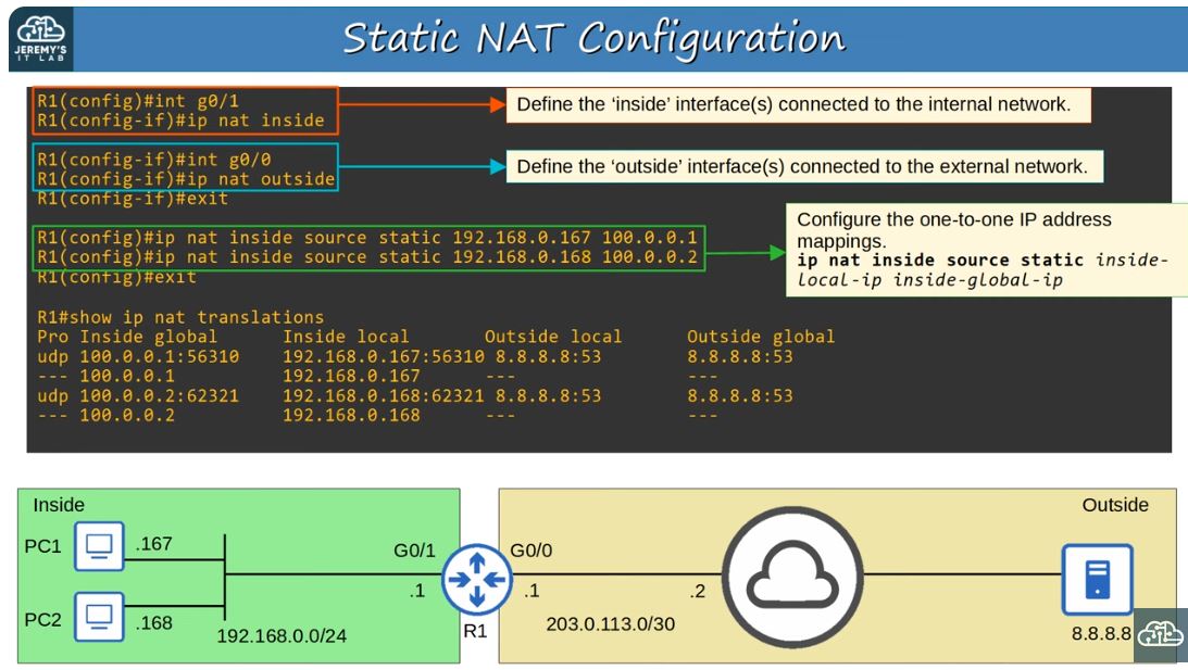
Cisco 128 - Static NAT
Configures static one-to-one mappings of private IP addresses to public IP addresses.
IP Address Terms:
- Inside Local = IP addr of the inside host from the perspective of the local network. Ex)192.168.0.167
- Inside Global = The IP address of the inside host AFTER NAT. Usually a public and routable IP address.
- Outside Local = IP address of outside host from the perspective of the local network. Ex) 8.8.8.8
- Outside Global = IP address of the outside host from the perspective of the rest of the world. Ex) Also 8.8.8.8
For our purposes these two addresses are usually the same for static NAT:
- Outside Local
- Outside Global

R1(config)#int g0/1
R1(config-if)#ip nat inside
R1(config)#int g0/0
R1(config-if)#ip nat outside
^ These two commands tell the router on which interfaces to enable NAT. One inside (internal), one outside (external).
R1(config)#ip nat inside source static <inside-local-ip-addr> <inside-global-ip-addr>
^ This configures the mapping of the internal IP address to the publicly routable external IP address.
Note that at first blush this makes static NAT seem useless because it still requires the same number of public routable IP addresses. It's not NAT behind a firewall like what we're used to. However, it truly provides NAT services - it "hides" the internal IP from the external world. It's just that each private internal IP address has to have an extra external IP address that it can use for Internet purposes.
Examples:
R1(config)#ip nat inside source static 192.168.0.167 100.0.0.1
R1(config)#ip nat inside source static 192.168.0.168 100.0.0.2
R1#ip nat translations
^ Shows what mappings exist and how they are being used. Look for port numbers on active "in use" IP addresses.
R1#ip nat statistics
^ Displays info about NAT such as how many NAT mappings have been defined, how many are dynamically in use, and which interfaces are confgured for static NAT.
R1#clear ip nat translation *
^ This clears all the dynamic (in flight) used NAT translations. (The mappings with port numbers will be removed).
[These are my notes from Jeremy's excellent CCNA course which can be viewed here.]
Monday, June 3, 2024
Cisco 127 - SSH and Telnet
Console Port Security:
By default, no password is needed when accessing via console port.
You can configure a password on the console line:
R1(config)#line console 0
^There is only one line, so number is always 0
R1(config-line)#password ccna
^Set the password
R1(conifg-line)#login
^Tells the device to require the password on the line
Alternative: Tell device to require usernames instead of a shared password
R1(config)#username smith secret Sammywich
^Creates a user named 'smith' with password 'Sammywich'
R1(config)#line console 0
^Same as previous config, switch over to the console line
R1(config-line)#login local
^Configure device to require a username to gain entry
Assign an IP address to a Layer-2 switch:
Q) Since switches are layer 2, how can we SSH to them?
A) Create a switch virtual interface (SVI) and assign the SVI an IP address. You'll also need to define a default gateway.
SW1(config)#interface vlan1
^Define the SVI
SW1(config-if)#ip address 192.168.1.253 255.255.255.0
^Assign an IP address to the SVI
SW1(config-if)#no shutdown
^Turn on the interface
SW1(config-if)#exit
SW1(config)#ip default-gateway 192.168.1.254
^Configure a default gateway for the switch
Telnet Config:
We are unlikely to enable telnet, but we can learn from looking at it
SW1(config)#enable secret ccna
^Require a password to access privileged exec mode. If we don't do this, we can't get to it via Telnet/SSH.
SW1(config)#username smith secret Sammywich
^Define a local username
SW1(config)#access-list 1 permit host 192.168.2.1
^Create an access-list that we can later assign to a telnet line so we can restrict it to allow incoming connections from a single IP address
SW1(config)#line vty 0 15
^Instead of configuring a single console line, this time we are configuring Virtual TeleType lines 0 through 15 (all of them).
SW1(config-line)#login local
^Require the use of locally defined usernames
SW1(config-line)#exec-timeout 5 0
^Define an inactivity timer of 5 minutes 0 seconds. After this, your session gets disconnected.
SW1(config-line)#transport input telnet
^Restrict these lines to telnet only. No SSH or RLogin.
Other options:
transport input telnet - Only Telnet
transport input ssh - Only SSH
transport input telnet ssh - Both
transport input all - All connections (including telnet, SSH, Rlogin, and more)
transport input none - Nope, nada
SW1(config-line)#access-class 1 in
^Similar to Standard ACLs, this assigns the access list previously defined about a dozen lines up to these lines on incoming sessions.
SSH Config:
Use v2, not v1.
"v1.99" = Supports both v1 and v2
Telnet = TCP port 23
SSH = TCP port 22
You will need an RSA key of at least 768 bits for SSH v2.
Before proceeding, define the hostname and domain name.
Switch>en
Switch#conf t
Switch(config)#hostname SW1
^Configure the device's hostname
SW1(config)#ip domain name jeremysitlab.com
^Configure the device's domain name
SW1(config)#crypto key generate rsa
^This generates the RSA public and private key pair that you will need later. Jeremy uses 2048 as the number of bits int he modulus. Don't fall for the [512] default because we know it needs to at least be 768.
Instead of interactively choosing the modulus length, maybe use this command:
SW1(config)#crypto key generate rsa modulus 2048
(Some countries may need to use smaller modulus lengths due to USA's encryption laws.)
Next 3 commands are the same as Telnet was (above) (except I'll replace "Telnet" with "SSH":
SW1(config)#enable secret ccna
^Require a password to access privileged exec mode. If we don't do this, we can't get to it via Telnet/SSH.
SW1(config)#username smith secret Sammywich
^Define a local username
SW1(config)#access-list 1 permit host 192.168.2.1
^Create an access-list that we can later assign to an ssh line so we can restrict it to allow incoming connections from a single IP address
SW1(config)#ip ssh version 2
^Configure for SSH v2
Next 5 commands are same as Telnet (except for SSH):
SW1(config)#line vty 0 15
^Instead of configuring a single console line, this time we are configuring Virtual TeleType lines 0 through 15 (all of them).
SW1(config-line)#login local
^Require the use of locally defined usernames
SW1(config-line)#exec-timeout 5 0
^Define an inactivity timer of 5 minutes 0 seconds. After this, your session gets disconnected.
SW1(config-line)#transport input ssh
^Restrict these lines to ssh only (no telnet).
SW1(config-line)#access-class 1 in
^Similar to Standard ACLs, this assigns the access list previously defined about a dozen lines up to these lines on incoming sessions.
[These are my notes from Jeremy's excellent CCNA course which can be viewed here.]
Cisco 126 - Syslog
R1(config)#logging console <severity>
^ Sets the level at which messages will be displayed, from <severity> up to and including 0. So, by specifying "6" (Informational), levels 0 through 6 will be displayed on the console.
Enabled by default at level 7.
Level = Keyword
0 = Emergency
1 = Alert
2 = Critical
3 = Error
4 = Warning
5 = Notice
6 = Informational
7 = Debugging
Mnemonic aid:
Every Awesome Cisco Enginer Will Need Ice cream Daily
R1(config)#logging monitor <severity>
^ Displays syslog messages on ssh/telnet
R1(config)#logging buffered [size] <severity>
^ Stores syslog messages in buffer (memory). Size = buffer size in bytes. Bigger number = bigger log but takes away space from operating memory.
R1(config)#logging <server-ip>
R1(config)#logging host <server-ip>
^ These two commands are the same. Configures device to send syslog messages to external central server which can collect logs from multiple devices for later analysis.
R1(config)#logging trap <severity>
^ Sets the level that will be sent to the external server.
R1(config)#terminal monitor
^ Syslog messages won't be displayed via Telnet/SSH unless you tell them to with this command.
R1(config)#logging synchronous
^ Displays syslog messages on their own line, not in the middle of my console entries.
R1(config)#service timestamps [datetime | uptime]
^ Controls whether syslog entries are displayed with date and time vs. system uptime.
R1(config)#service timestamps log datetime
R1(config)#service sequence-numbers
^ These two commands tell the device to display both date and sequence number in syslog messages.
[These are my notes from Jeremy's excellent CCNA course which can be viewed here.]
Cisco 125 - SNMP
R1(config)#snmp-server contact admin@MyCompany.com
R1(config)#snmp-server location IT Suite Lab A
^Set contact info & location of device
R1(config)#community MyPassword1 ro
R1(config)#community MyPassword2 rw
^ Sets the community strings (passwords) for read only and read/write
R1(config)#snmp-server host 192.168.1.1 version 2c WhoDat1
^ Configures the IP address of the NMS, SNMP version, and which community string to use with this server
R1(config)#snmp-server enable traps snmp linkdown linkup
R1(config)#snmp-server enable traps config
^ Set linkdown/up traps and configuration traps to the NMS monitor
[These are my notes from Jeremy's excellent CCNA course which can be viewed here.]
Subscribe to:
Comments (Atom)